How to Connect IR LED to Arduino Pro Micro: Complete Guide
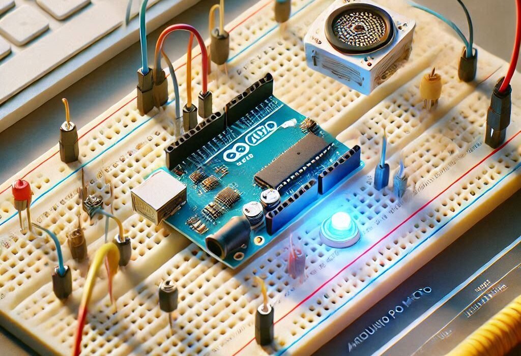
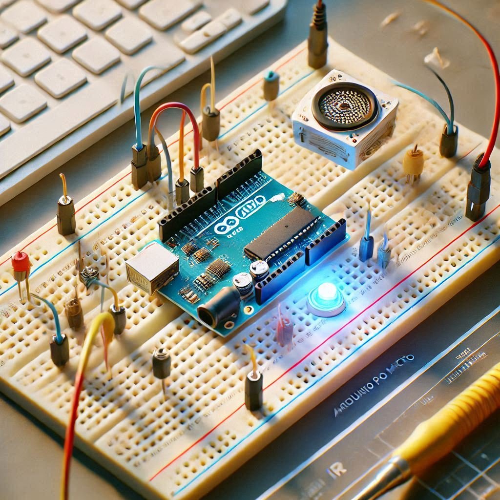
It is interesting to automate controlling TVs or LED strips with an IR remote and an Arduino. This time, I will show you how to connect IR LED to Arduino Pro Micro and provide some ways to get the very best performance out of it. If you’re constructing a home automation system or a custom controller, this tutorial would be a great way to begin.
What Is The Need for Using an IR LED with Arduino Pro Micro?
It is reliable and inexpensive and can be used for remote control of devices. With an Arduino Pro Micro and a strong IR LED, one can:
- Use IR appliances without being in the direct vicinity of the device (continue to use when the high powered LED is used).
- Construct IR solids that work as remote controls for TVs, air conditioners, or any other similar devices.
- Create compact embedded systems or portable electronic devices.
Challenges in IR LED Projects
- Possessing the capability of long-range IR communication is not easy.
- When there are high powered IR LEDs, the issue of power management arises.
- The protocol and wiring complexity of the IR is also not clear or easy.
Let’s address these challenges step by step.
Components Needed
In this challenging process of How to Connect IR LED to Arduino Pro Micro, the components needed are as follows;
| Component | Quantity | Description |
| Arduino Pro Micro | 1 | Microcontroller for the project |
| IR LED (940nm, 5W) | 1 | High-powered LED for broader coverage |
| IR Receiver (1838B) | 1 | To receive IR signals from the remote |
| N-Channel MOSFET | 1 | For switching and controlling the IR LED |
| Resistors (10Ω, 220Ω) | 2 | Current limiting and pull-down purposes |
| 12V Power Supply | 1 | To power both Arduino and the IR LED |
| Breadboard and Wires | As needed | For prototyping the circuit |
Steps for how to Connect IR LED to Arduino Pro Micro
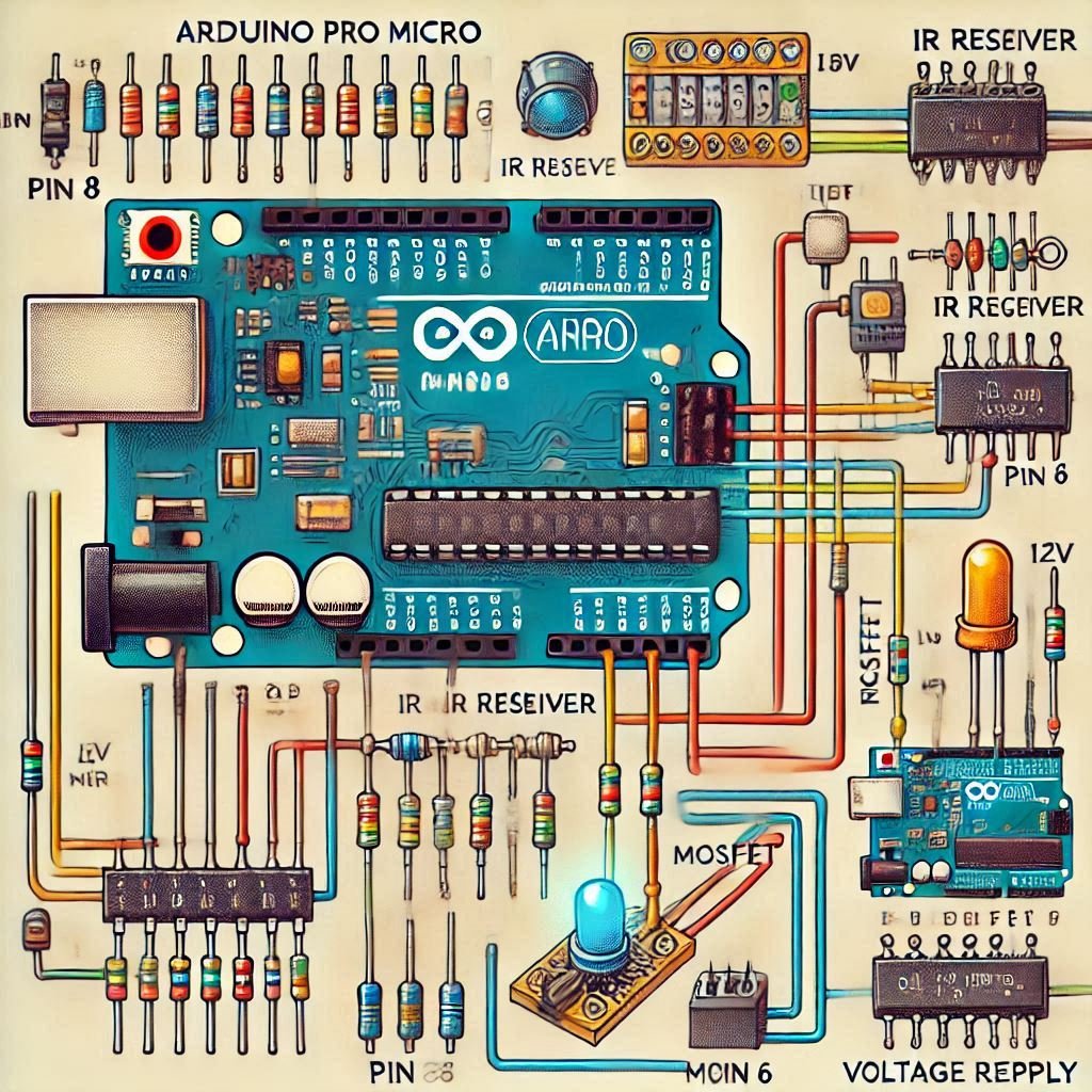
Understanding the Circuit Diagram
The circuit consists of the following main connections:
IR Receiver to Arduino Pro Micro
- GND (IR Receiver) → GND (Arduino)
- VCC (IR Receiver) → 5V (Arduino)
- Signal Pin → Digital Pin 8 (Arduino)
High-Powered IR LED to Arduino via MOSFET
- Drain (MOSFET) → Negative Pin of IR LED
- Source (MOSFET) → GND
- Gate (MOSFET) → Digital Pin 6 (Arduino) (via a 10Ω resistor)
- Positive Pin of IR LED → 12V Power Supply
Power Supply for Arduino and LED
- Use a 12V to 5V voltage regulator to supply power to the Arduino.
- Split the power supply: 12V goes to the IR LED and the voltage regulator.
Assembling the Circuit
Wiring Tips:
- Use solid-core wires for stable connections.
- Ensure proper insulation to prevent short circuits.
- Use double-sided tape to secure components on a small breadboard.
Safety Tips:
- Disconnect the power supply before making any changes.
- Avoid exceeding the maximum current rating of the IR LED.
Testing the Setup
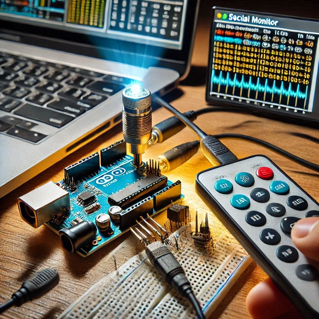
- Connect the circuit to your power supply.
- Use a remote control to send IR signals to the receiver.
- Observe the IR LED flashing as per the programmed commands.
Optimizing Performance
- Adjust Current: Use a current-limiting resistor to control the IR LED’s brightness and range.
- Enhance Signal Strength: Position the IR LED for optimal coverage without obstructions.
- Debugging: Use the serial monitor to log IR signals and troubleshoot issues.
Applications of IR LED and Arduino Pro Micro
Firstly we discussed how to connect IR LED to Arduino Pro Micro. Now following are the applications:
- Universal Control: One remote to rule them all. This does away with multiple remotes, and even the clutter of remotes and makes daily actions easier.
- Integrating Smart Home: Allows control of devices connected via IR blaster It makes smart homes more convenient and more automated.
- IoT Projects: Pair with Wi-Fi modules for remote awareness It helps to keep integration seamless and functional to the project.
- Game Controllers: IR-based controls over traditional inputs It offers a fun and new way of controlling games.
Conclusion
By following this guide, you’ve learned how to connect IR LED to Arduino Pro Micro and successfully use it in remote control applications. This configuration is universal and portable and is a great first step into the world of wireless communication in electronics. Whether a beginner or a pro, there is a lot of room for creativity in this project.
Frequently Asked Questions (FAQs)
How do I connect an IR sensor to my Arduino?
To connect an IR sensor, connect its VCC pin to the Arduino’s 5V, the GND pin to GND, and the Signal pin to a digital input pin (e.g., Pin 8). Ensure proper wiring, and use a library like IRremote to decode signals.
How to connect an IR transmitter to Arduino?
Connect the positive leg of the IR transmitter LED to a digital pin (e.g., Pin 3) via a current-limiting resistor, and the negative leg to GND. Use a suitable library to send IR signals based on your application.
How can an IR remote be used in an Arduino project?
An IR remote sends encoded signals to the IR receiver connected to the Arduino. By decoding these signals using the IRremote library, you can control LEDs, appliances, or other devices based on the button pressed on the remote.
Can I use a regular LED instead of a high-powered IR LED?
Yes, however, it must be pointed directly at the target and its range would be limited.
Do I need a heat sink for the high-powered LED?
In case of continuous operation, a heat sink can be added for better heat dissipation.
How do I control both voltage and current?
For voltage control, a voltage regulator is useful. For current control, you may use a resistor or a constant-current driver.


